Well Stimulation, Wireline & Flow Control Equipment
for the Oil and Gas Industry
Well Stimulation, Wireline &
Flow Control Equipment
for the Oil and Gas Industry
GKD Ball Injectors
Spanish version - Inyector De Bolas (PDF)
Functionality
The GKD Ball Injector, also known as a "Ball Gun" or a "Ball Sealer" is used to inject balls into a pressurized acid solution (Fracture Acidizing or Matrix Acidizing) via the surface treating lines. The balls are carried by the fluid flow towards the perforations until they seat against the open perforations, at which point the acid and an increased pressure is applied against the perforations that are not open or not fully open.
This reaction opens more perforations to the acid and repairs well bore damage - Matrix Acidizing. At higher pressures Fracture Acidizing is used to enlarge the effective wellbore. In both cases, the result is targeted fluid control, minimized fluid loss, reduced skin damage and improved flowback.
Once the pumping stops, the injected balls float to the top of the well if positively buoyant, sink to the bottom if negatively buoyant, and dissolve if biodegradable.
Video - Animation of the GKD Ball Injector with remote controlled motor drive, used for well stimulation in the oil industry.
Operation
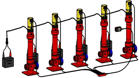
The balls can be injected by manually turning the Ball Injector’s vane shaft with the supplied hand crank. However, because of the dangers involved in working with large volumes of high strength acid at high pressures, most service companies use the remote controlled GKD Motor Drive Package, which is now available in a Multi-Drive configuration whereby a single Remote Control can operate up to five Ball Injectors providing 1,000 Ball Capacity (750 balls for Model 2021).
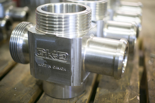
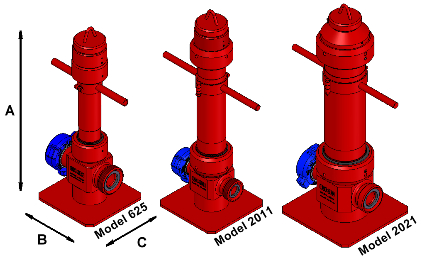
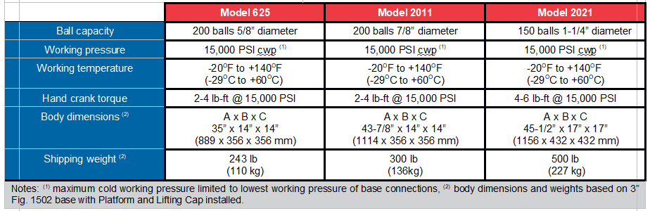
Main Body Specifications
Standard base configurations: Fig. 1502, Fig. 1002 and Fig. 602 in 2", 3" and 4" sizes; detachable wing nuts are included
Standard equipment: Lifting Cap, Carrying Handle, Hand Crank and Spanner, Operating Service Manual and Documentation Package consisting of hydrostatic pressure test graph and material certifications for all critical components
The newly redesigned GKD Multi-Drive Motor Package allows a single Remote Control to simultaneously operate up to five Motor Drives. This is done via the GKD Smart Hub and allows users to inject, sequentially or simultaneously, up to 1,000 Diverter Balls (750 Balls for Model 2021) without reloading. Each Motor Drive requires its own 12-volt power source located within 20' (6m), typically an automotive battery.
Remote Control
Controls single Motor Drive directly or multiple Motor Drives through the GKD Smart Hub
Automatic and manual modes of operation
Injection speed adjustment from 1 to 220 balls per minute in automatic mode
Colour LCD Display provides real-time information on injection speed and quantity of balls discharged
Overload injection alarm indicator light with reverse button and reset switch
Working temperature range of -20°F to +140°F (-29°C to +60°C)
Dimensions: 7" L x 3-3/4" W x 2-5/8" H (178 mm x 95 mm x 67 mm), weight 1.75 lb (0.80 kg)
GKD Smart Hub
Used to connect the GKD Remote Control to up to five (5) GKD Motor Drives
Not required if the GKD Remote Control operates only one (1) GKD Motor Drive
No separate power supply required
Working temperature range of -20°F to +140°F (-29°C to +60°C)
Dimensions: 9” L x 4-3/4” W x 1-7/8” H (228 mm x 121 mm x 48 mm), weight 3 lb (1.36 kg)
Motor Drive Specification
12 V DC motor coupled with planetary gear system connected to12V vehicle battery via heavy duty 20’ (6 m) Power Cable utilizing military spec environmental resistant connectors
Utilizes an anodized aluminum housing with plated or stainless-steel parts throughout for corrosion resistance
Manual pressure equalizing valve enables pressure or vacuum relief if required.
Anti-vibration spring-loaded nut with safety latch assembly prevents accidental loosening of motor drive from the main body during operation
Dimensions: 12-3/8” L x 6-3/8” D (314 mm x 162 mm), weight 24 lb (10.9 kg)
Working temperature range -20°F to +160°F (-29°C to +70°C)
Motor current consumption: 38-42 AMP @15,000 PSI
Maximum injection rate at 15,000 PSI; 240-280 balls/minute (Remote control set to manual mode)
GKD Industries Ltd.
7939 54 Street SE
Calgary, Alberta
Canada T2C 4R7
Location map